Our Services
One system does not fit all foundation problems
PUSH PIER UNDERPINNING SYSTEM
THE SYSTEM
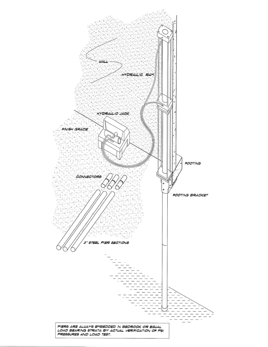
The push pier foundation underpinning system is a method that utilizes steel pipe pilings to permanently support structures experiencing vertical foundation settlement. The steel piers are hydraulically driven through non-supporting soil until embedment in bedrock, or load bearing material is verified. The new foundation elements therefore transfer the weight of the structure through non-supporting foundation soil to a competent underlying material. The piers can be effective to depths in excess of 75 feet and have a yield strength of 70,000 lbs. and a tensile strength of 80,000 lbs. Professionally designed coatings or a cathodic protection system are used to protect the piers from corrosion.
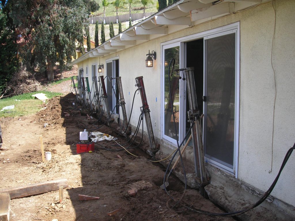
TYPICAL INSTALLATION
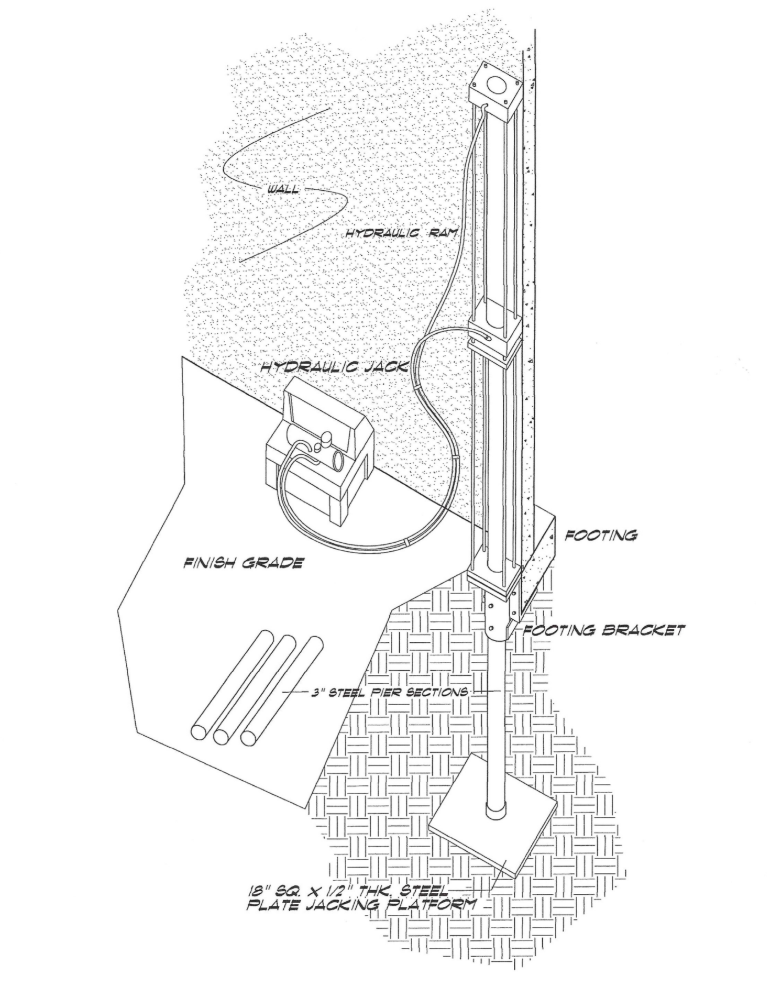
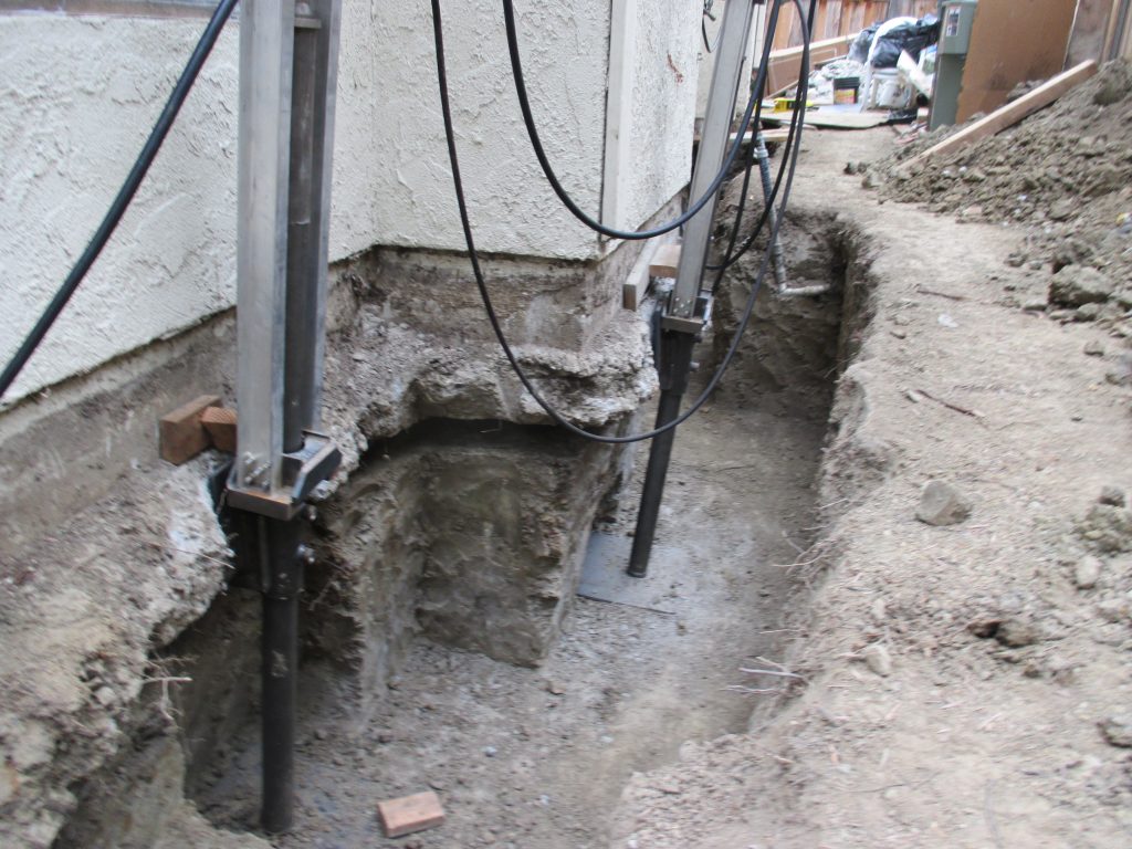
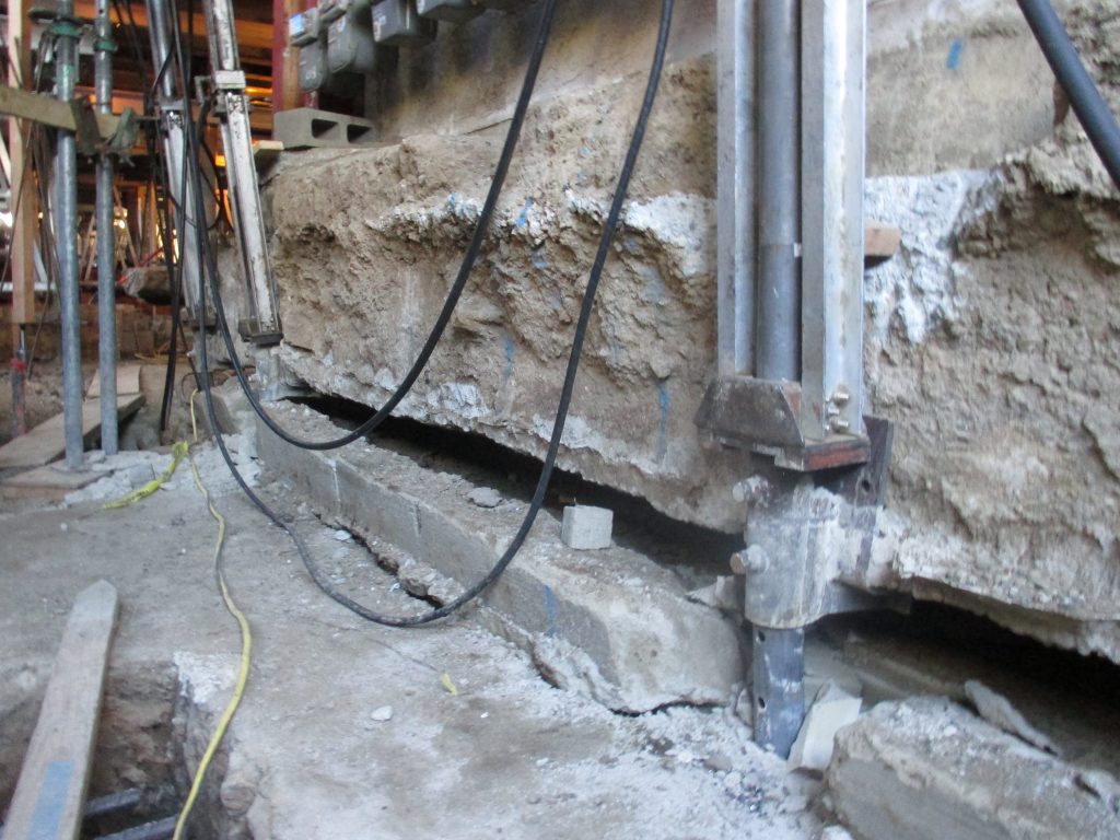
The steel piers are positioned according to engineered structural calculations for
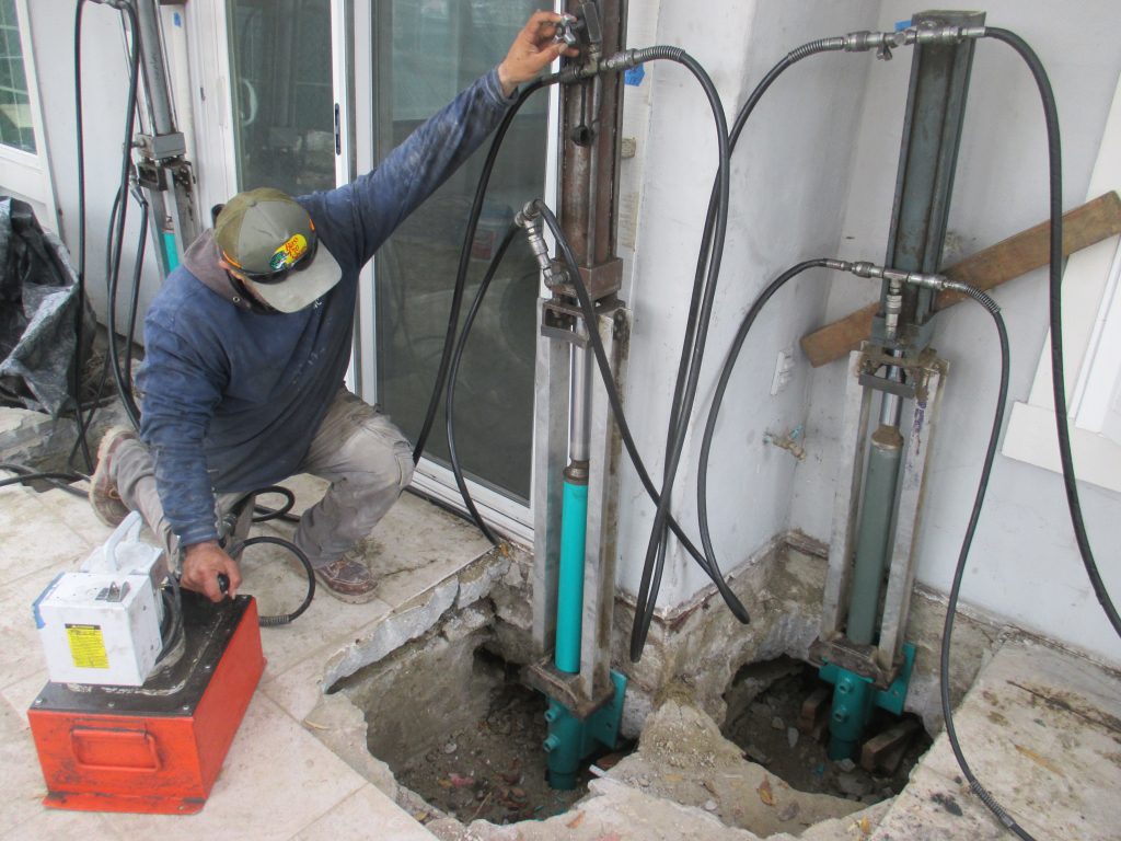
allowable bending moment capacity of the footing and structural loading on each pier. The piers are typically calculated to be spaced and installed at 6 to 8 feet on-center at exterior and interior foundations. An excavation of approximately 2 x 3 feet is made alongside the foundation where the piers are to be installed. Structural steel angel brackets are then placed under the footing whereon hydraulic rams are attached to each bracket. Three ft. lengths of 3-inch diameter carbon steel tubing are then mounted under the hydraulic rams and driven through the bracket assembly into the ground by hydraulic pressure, utilizing the concrete footing as the reaction point. An oversized “frictionless end” or foot is attached to the bottom of the first pier section, leaving an annular space around the pipe reducing side friction and concentrating resistance at the end of the pier. Additional 3 ft. sections of tubing are aligned and tightly attached by steel connector sleeves as the pipe support column is lengthened to allow it to be driven through the non- supporting soil, until bedrock or load bearing strata is reached. A Geotechnical investigation is generally performed prior to commencement of construction, which usually determines the depth to bedrock or bearing material. The installation of each pier is closely monitored and documented to assure the pipe piles are embedded to the target depth and pressure.
LOAD TEST
The most critical feature of the system is the verification of the ultimate load capacity for each pier. The load tests are initiated by installing the piers one at a time, as the reaction is equal to a large area of weight because of the spanning of the foundation and load disbursement of the building. While the piers are being driven to bearing material, the competency of the subsurface soil is monitored by documenting psi pressures for each three-foot pier section. The piers are driven until the optimum static load (minimum 24,870 lbs.) can be sustained and tested without further penetrating the soil. With the force exerted by the structure uniformly distributed among all the piers, the weight of the building on any individual pier is substantially below the ultimate load capacity of each
pier. In consideration of these parameters, the settlement potential of the piers is
generally considered negligible. The design of the piers can be altered, or the span can be adjusted to allow for variations in load factors.
LIFTING STRUCTURES
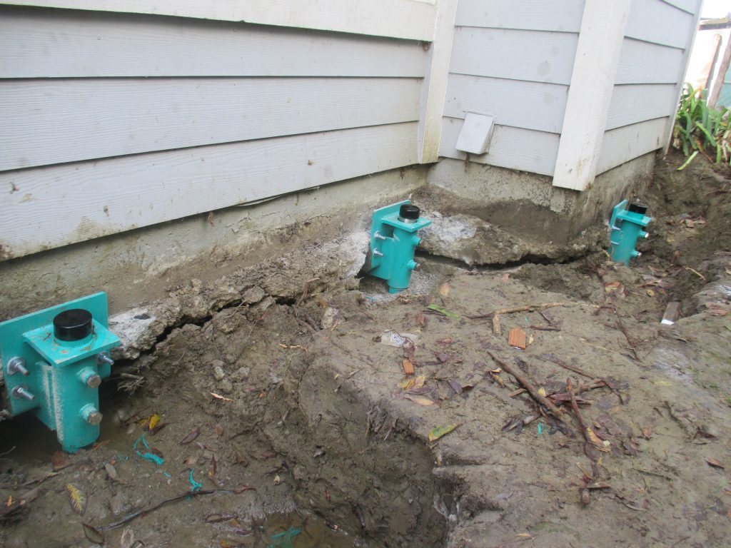
A special advantage of the system is the ability to precisely re-level structures with a controlled hydraulic lift. The lifting process is performed after the piers have been installed and field tested. The hydraulic rams, which have independent controls, are fitted on each pier, enabling them to function simultaneously or individually to correct as little as .01 inch or in excess of 10 inches. While the controlled re-leveling is occurring, continues floor level manometer readings are conducted to ensure the foundation is precisely brought back to the proper elevation. Once the re-leveling is complete the steel piers are permanently bolted to the foundation brackets. The interior slab is then cored
and slurry is injected beneath the footing and slab to fill the voids created by the lifting process.
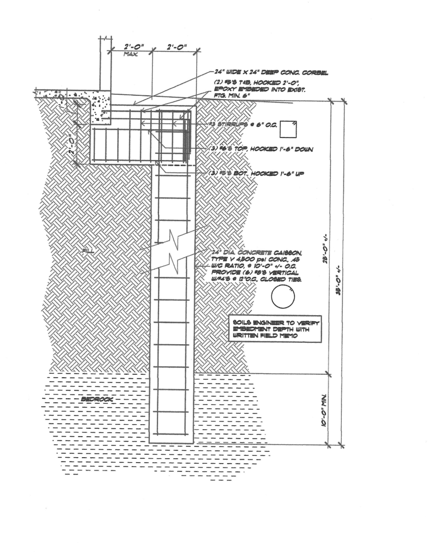
CAISSONS & GRADE BEAMS
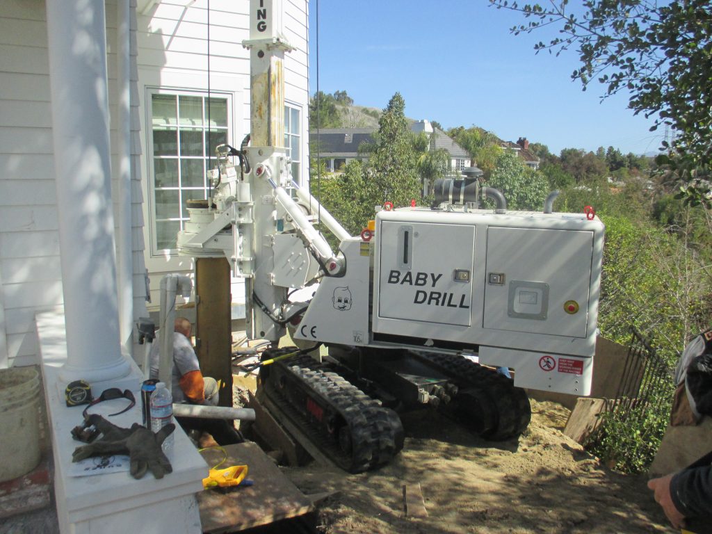
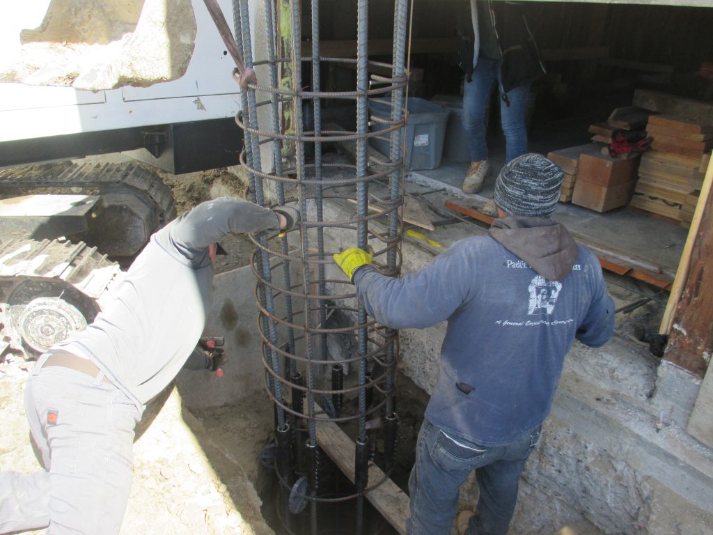
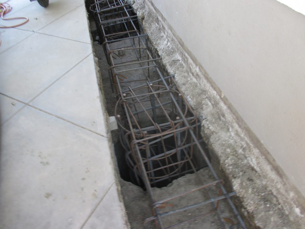
Caissons are most frequently utilized on hillside properties that are suffering distress due to lateral slope influences. Caissons also known as drilled piers and CIDH (cast in drilled hole) requires the drilling of vertical shafts with embedded structural steel (re-bar or I-beams) and concrete throughout to bear the foundation loads and create lateral stability. Caissons are also used to support retaining walls on hillsides and used in earth retention systems which are commonly referred to as soldier piles.
The caisson & grade beam system used for underpinning foundations typically consists of drilling 18” to 30” diameter holes adjacent to the perimeter foundation at 8 to 12 ft. on-center embedded into the underlying bedrock or bearing strata. Once the holes of predetermined diameters and depths are drilled re-bar cages are installed and the shafts are poured with concrete. The caissons are then attached to the existing foundation with a continues reinforced concrete grade beam & corbel system which distributes the building loads to the caissons to prevent any further building distress caused by vertical or lateral soil movement.
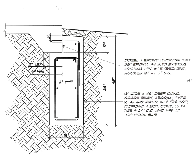
DEEPENED FOOTINGS
Deepened footings also referred to as concrete cut-off walls, grade beams or continues underpinning footings are primary used to stabilize structures that are affected by expansive soils. They can also be used to strengthen inadequate or poorly constructed original foundation systems along with providing support through shallow non- supporting soils. Expansive soil movement is an on-going process due to seasonal climate changes that result in cyclic wetting and drying of the surface soils supporting the foundation. Structural distress caused by the on-going shrinking and swelling of the underlying expansive soils causes distortions and deflection of the foundation and building to occur. A professionally designed and installed deepened footing will mitigate future distress by extending the foundation support to a more stable level where moisture changes in the soil are less active. Additionally, it will act as a cut-off wall to inhibit transmission of water beneath the foundation and thereby reducing the potential of shrinking and swelling of the underlying expansive soils while strengthening and increasing the foundation stiffness.
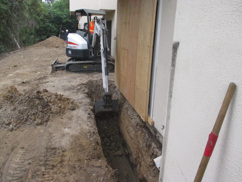
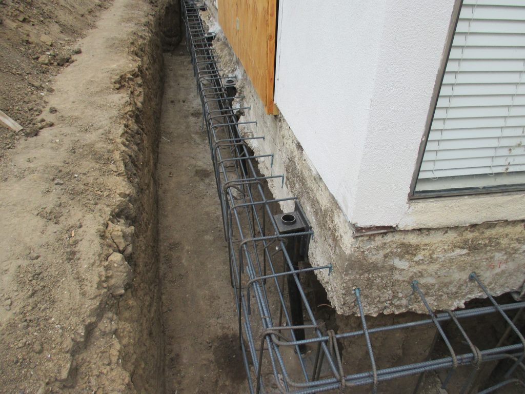
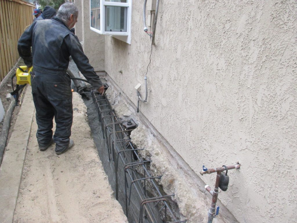
The continues deepened footing is installed beneath the existing perimeter foundation to design depth typically ranging from 3 to 5 feet. The installation procedure consists of installing our specially fabricated shoring jacks typically at 6 to 8 ft. on-center beneath the perimeter foundation. The foundation is then re-leveled (if required) and the sacrificial shoring jacks are locked in place. A trench is then excavated beneath the existing footing to a predetermined depth and rebar dowels are epoxied into the existing footing to provide a positive connection to the new footing. Reinforcing steel is then installed in the footing trench, wherein the concrete is monolithically poured to complete the installation of the supplemental foundation.
DRAINAGE AND WATERPROOFING
Proper implementation of drainage & grading is essential to prevent water related
foundation and slope issues especially for structures located on hillsides and expansive soil. Additionally, a professionally installed drainage and waterproofing system will eliminate water intrusion issues.
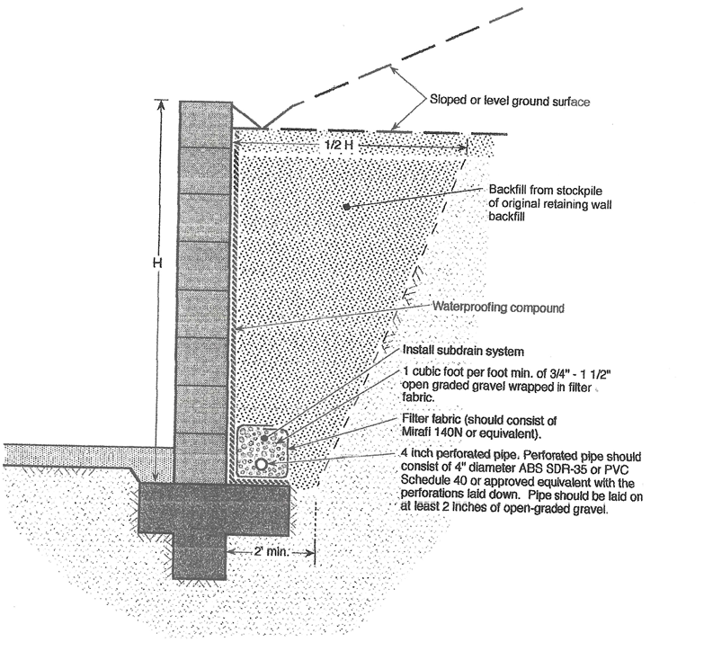
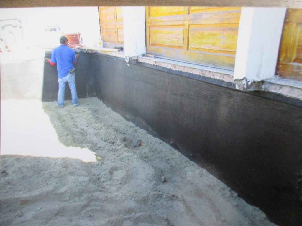
FRENCH DRAINS & WATERPROOFING
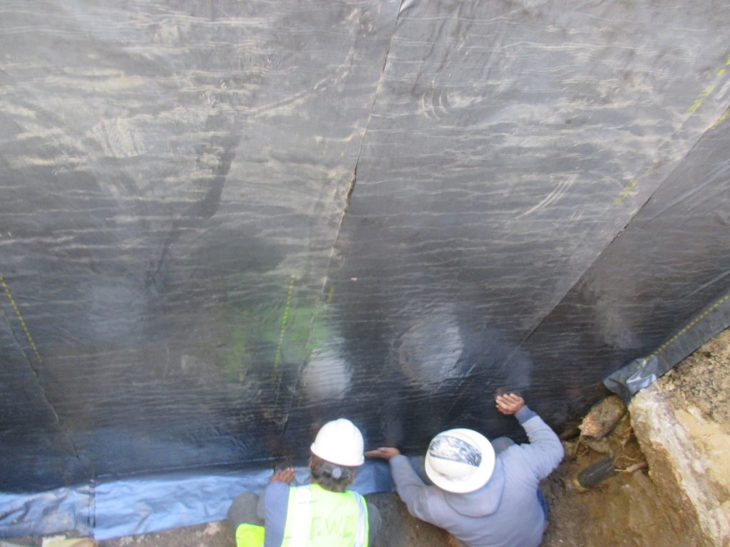
French drains may be used adjacent to foundations or areas where water is migrating into the soils. They are also used on the backside of retaining walls to prevent hydrostatic pressure which could potentially cause failure. French drainage systems create an underground channel to funnel water away from structures and eliminate water intrusion and dampness when installed with the proper waterproofing. A French drain consists of installing a perforated drainpipe in a trench or at the base of a wall or foundation which is covered in gravel and wrapped in filter fabric in order to prevent loose soil from collecting in the drain. The perforated pipe is ultimately connected to a solid pipe to transfer the collected water to a safe outlet point. Waterproofing and drainage panels are installed on retaining & foundation walls prior to installation of the sub drain to prevent moisture penetration.
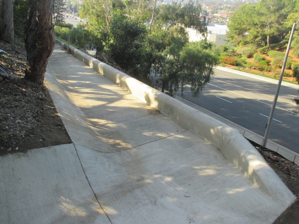
GRADING & SUBSURFACE DRAINAGE SYSTEMS
Poor surface drainage can lead to saturation of subsurface soils which may cause distress to structures as a result of soil expansion and/or settlement along with potentially causing surficial slope failures. All landscaped areas within 10 feet of the foundation should have a gradient of at least 5 percent away from the building, and the flatwork should have a gradient of at least 2 percent. Earthen berms or hardscape should be installed at tops of slopes to prevent water runoff onto the hillside. A subsurface drainage system with area and/or channel drains should be installed to collect and transfer the diverted surface water to a safe outlet point. Additionally, the drainage system can be used to collect water from gutters and down spouts.
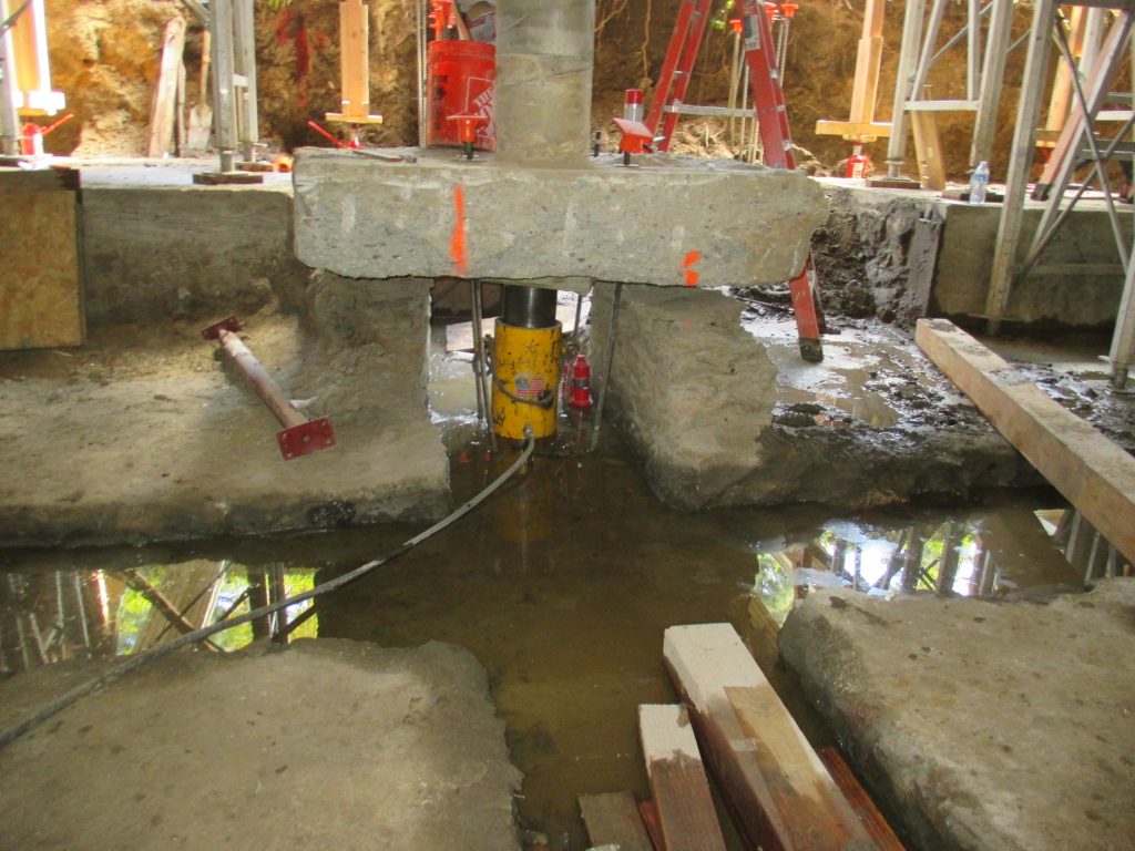
FOUNDATION LIFTING
Foundation re-leveling is performed when a building has settled due to adverse
underlying soil and foundation conditions. Structural underpinning & foundation repairs are typically performed in conjunction with the building re-leveling to prevent any future movement. Pacific Western Engineering Contractors, Inc. has lifted hundreds of building units throughout Southern California and has a huge fleet of specially built hydraulic rams, pumps & components to lift many types of structures. The foundation re-leveling system provides for the precise re-leveling of structures with a controlled hydraulic lift to minimize damage during the jacking process. The system can correct as little as ¼-inch or more than 10-inches of floor deflection.
The system consists of installing large steel jacking plates beneath the existing footing typically spaced at 6 to 8 feet-on-center at exterior and interior foundations that require lifting. Specially fabricated foundation brackets are then installed under the footing whereon hydraulic rams, which have independent controls, are attached to each bracket. A structural steel pipe is then mounted under each hydraulic ram and installed through the bracket assemblies and fitted into the prefabricated connection sleeve in the center of the jacking plate. Once all the foundation brackets, jacking platforms, lifting pipes and hydraulic rams are set and load tested they are hooked together with hydraulic hoses to a series of hydraulic pumps and actuated simultaneously to lift and level the foundation. While the controlled re-leveling is occurring continues floor level manometer readings are conducted to ensure the foundation is precisely brought back to the proper elevation. Once the re-leveling is complete the pipes are bolted to the foundation brackets, rams removed, and tops of the lifting pipes cut off. The designed underpinning system can then be installed to permanently stabilize the foundation in the re-leveled position, utilizing the jacks as temporary shoring and sacrificing them in place upon completion.
Fast And Reliable Services for all your projects
ALL COMPONENTS LOCALLY FABRICATED AND MADE WITH
STEEL FROM THE USA